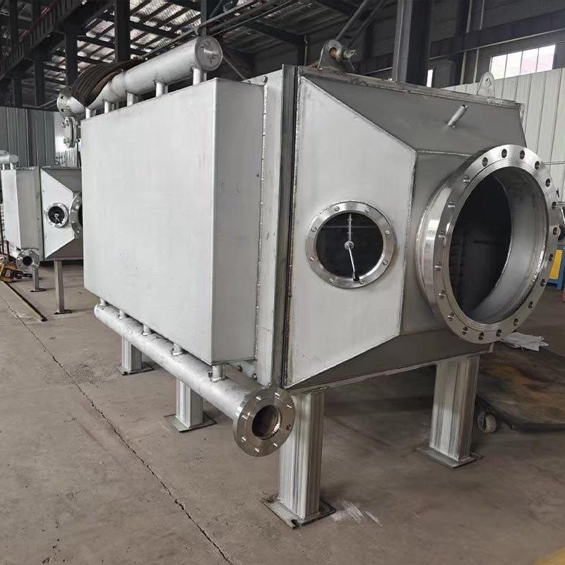
The GJ-CP03 Finned Heat Exchanger is a highly efficient heat transfer solution designed to improve thermal performance in systems where one of the working fluids—typically air or gas—has relatively low thermal conductivity. By adding specially designed fins to the surface of the base tube or plate, the heat transfer area is significantly increased, allowing the system to achieve higher efficiency within a compact structure.
The GJ-CP03 Finned Heat Exchanger is a highly efficient heat transfer solution designed to improve thermal performance in systems where one of the working fluids—typically air or gas—has relatively low thermal conductivity. By adding specially designed fins to the surface of the base tube or plate, the heat transfer area is significantly increased, allowing the system to achieve higher efficiency within a compact structure.
Finned heat exchangers are widely used in air heating, cooling systems, waste heat recovery, and industrial process applications. Their ability to enhance heat transfer between gases and liquids makes them an ideal solution for industries that require efficient energy utilization and reliable thermal performance.
MG-TECH’s finned heat exchangers are engineered to deliver high heat transfer efficiency, flexible structural design, and reliable operation under complex industrial conditions.
The addition of fins to the surface of the base tube dramatically increases the effective heat transfer area. This allows the exchanger to compensate for the low heat transfer capability of gases or low-conductivity fluids and significantly improves overall thermal efficiency.
Finned heat exchangers can be manufactured with various fin structures, including:
Flat fins
Corrugated fins
Serrated fins
Perforated fins
This flexibility allows the design to be optimized for different operating environments and performance requirements.
By selecting suitable materials and reinforced structures, the finned heat exchanger can operate effectively in high-temperature environments, waste heat recovery systems, and high-pressure refrigeration processes.
The fin material is generally cost-effective, and the improved heat transfer efficiency allows the system to achieve the same performance with a smaller equipment size, reducing overall investment costs. In addition, the modular structure allows easier cleaning and maintenance, and certain designs can be partially disassembled when necessary.
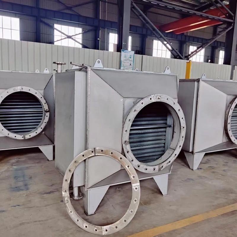
A finned heat exchanger works by increasing the surface area available for heat transfer. The fins are attached to the outer surface of the base tube or plate, allowing heat to transfer more effectively between the fluids.
Typically, one fluid flows inside the tubes, while the other fluid—often air or gas—flows over the finned surfaces. The fins extend the heat transfer area and improve contact with the flowing fluid, which significantly enhances the rate of heat exchange.
This design is particularly effective in systems where the external medium has low thermal conductivity, as the fins help accelerate heat transfer and improve overall system efficiency.
Significantly increased heat transfer surface area
High thermal efficiency for gas-to-liquid heat exchange
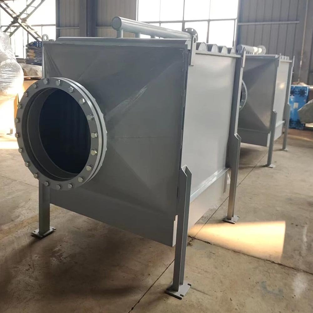
Compact and lightweight design
Flexible fin structures for different applications
Suitable for high-temperature and industrial environments
Lower operational and installation costs
Easy cleaning and maintenance
Finned heat exchangers are common heat exchange equipment compared with detachable plate heat exchangers and shell and tube heat exchangers. They have significant differences in structure, working principle, application scenarios, etc. The following are their main differences:
| Characteristic | Finned Heat Exchanger | Detachable Plate Heat Exchanger |
|---|---|---|
| Heat Transfer Efficiency | High gas-side efficiency (fin-enhanced surface area)36 | Superior overall coefficient (turbulence-enhanced flow)37 |
| Pressure Drop | Low gas-side resistance (optimized fin design)3 | Significant (complex flow channels)6 |
| Pressure Resistance | High (robust base tube structure)3 | ≤2.5 MPa (gasket limitations)67 |
| Suitable Media | Gas-liquid/gas-vapor multiphase flows3 | Clean liquids/steam (anti-clogging design)67 |
| Maintenance | Challenging fin-side cleaning3 | Detachable plate cleaning system67 |
| Compactness | Bulkier (fin spacing requirements)3 | High density (1000 m²/m³ compact ratio)6 |
| Characteristic | Finned Heat Exchanger | Shell-and-Tube Heat Exchanger |
|---|---|---|
| Heat Transfer Efficiency | Enhanced convection (fin optimization)36 | Moderate (baffle-dependent flow)37 |
| Pressure Drop | Elevated (tortuous flow paths)3 | Reduced (streamlined configuration)6 |
| Pressure Rating | Medium-low (≤4.0 MPa)3 | High-pressure design (≤10 MPa)67 |
| Media Compatibility | Gas-gas/gas-liquid versatility3 | Liquid-liquid/high-viscosity fluids6 |
| Serviceability | Specialized tools required3 | Retractable tube bundle maintenance6 |
| Space Efficiency | Area/volume ratio >700 m²/m³3 | Spacious layout (maintenance allowance) |